Debugger-based On-Target Testing
System Testing

System testing with DOTT is also referred to as 'free running mode' testing. This essentially means DOTT is used to download the firmware to the target and boot it up and let the firmware run while providing external stimuli via the target's external communication interfaces.

To execute the included system test examples please use the reference target platform describe in setup section.

System (Free-Running) Test Examples

When implementing system tests, DOTT is used in free running mode where the target is running while external stimuli are provided and, at predefine points in time, the target's internal state is inspected using DOTT.

One way how to provide external stimuli to the external interfaces of a target is described in the section External Test Equipment. A simple system testing example which uses this approach together with the Reference Board is included in dott. The I2C connection between the reference board and the Raspberry Pi has to be established follows:

|---------------| SDA (GPIO2) SDA (D14) |-----------|
| RASPBERRY PI | <------------------------------> | STM32F072 |
| | | |
| | SCL (GPIO3) SCL (D15) | |
| | -------------------------------> | |
| pigpio daemon | | |
| | GND GND | |
|---------------| -------------------------------- |-----------|

Before executing the tests you need to edit the conftest.py file locate in the examples folder. In the function add an elif branch for your host machine as shown below. Replace YOUR_HOST_NAME with the host name of your machine where you run pytest and replace AAA.BBB.CCC.DDD with the IP address of your RaspberryPi where PiGPIOD is running.

def set_config_options():
# machine-specific settings (selected based on hostname)
# ...
if hostname == 'V1852354E':
# ...
elif hostname == 'YOUR_HOST_NAME':
DottConf.set('pigpio_addr', 'AAA.BBB.CCC.DDD') # remote PiGPIO daemon on your RaspberryPI

Executing Example Component Tests

Once the I2C hardware connection is established between target and RaspberryPi and and the GPIO daemon on the RaspberryPi is set up and running, the tests can be executed. To do so, open a Python command prompt (and activate the DOTT venv if using a virtual environment). In the command prompt now navigate to the examples\02_system_testing of the dott examples package downloaded from GitHub:

> cd dott_doc_examples_xxx\examples\02_system_testing\host
> dir
02.01.2019 08:22 2.008 dott.ini
02.01.2019 08:22 4.916 test_i2c_comm.py
02.01.2019 08:22 4.933 test_sysinit.py

Now you can no run the tests by calling pytest:
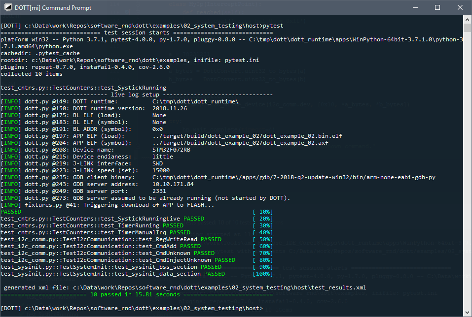
Example system tests using I2C as external target interface.

Understanding the Example System Tests

The target firmware for the example system tests are based on code generated with the STM Cube MX tool. The code base in the target folder includes the STM32 HAL library, CMSIS support code and peripheral initialization code. The actual code under test are located in Src/example.c and implements a simple command processor which receives commands from the host via I2C. The following table summarizes the core components of the example:

Content Source File
Timer functions on target examples/02_system_testing/target/Src/examples_cntr.c
Command functions on target examples/02_system_testing/target/Src/examples_cmd.c
counter tests on host examples/02_system_testing/host/test_cntr.py
system init tests on host examples/02_system_testing/host/test_sysinit.py
I2C command communication tests on host examples/02_system_testing/host/test_i2c_comm.py

System Initialization Tests

The following test is an example how DOTT can be used to test basic system initialization functionality. In the target firmware, there is a variable called *_sample_cnt* located in the BSS (meaning that the variable shall be zero-initialized by the compiler's runtime). It is a good practice to randomly check that zero initialization is performed as expected. The following test halts the target in the reset handler (i.e., before the compiler's runtime gets control), writes a well known pattern into the variable in BSS section and then continues target execution. The target is halted again when reaching main. There it is checked that the variable was initialized to zero by the startup code of the compiler's runtime.

# code snippet from test_sysinit.py
def test_sysinit_bss_section(self, target_load, target_reset):
# when entering the test the target is halted at the DOTT test hook
# create halt points in Reset_Handler and main
hp_reset = HaltPoint('Reset_Handler')
hp_main = HaltPoint('main')
# reset the target, let it run and wait until it has reached the reset handler
dott().target.reset()
dott().target.cont()
hp_reset.wait_complete()
# write some well known, non-zero pattern int a variable located in the BSS section
pattern = 0xaabbaabb
dott().target.eval(f'_sample_cnt = {pattern}')
assert (pattern == dott().target.eval('_sample_cnt')), 'expected to read back test pattern'
# continue and wait until main has been reached; the variable in bss shall now be zero
dott().target.cont()
hp_main.wait_complete()
assert (0x0 == dott().target.eval('_sample_cnt')), 'expected to read back zero'

A similar test called test_sysinit_data_section can also be in test_sysinit.py. This one checks that a variable located in the data section is properly initialized by the compiler's runtime (i.e., the initial content of the variable was correctly copied form FLASH memory to RAM).

Systick Tests and Live Access

A standard feature of Cortex-M MCU frequently used together with an RTOS is the Systick timer. With DOTT it is easy to (roughly) check if the systick counter was configured correctly and is advancing as expected. The following test shows how to do that:

# the following code is from file test_cntr.py
def test_SystickRunning(self, target_load, target_reset):
assert (0 == dott().target.eval('_tick_cnt')), 'Systick count shall initially be zero.'
dott().target.cont()
time.sleep(2)
dott().target.halt()
assert (2000 <= dott().target.eval('_tick_cnt')), 'Systick counter should have advanced while target was running'

An alternative implementation shown next uses DOTT's live access feature which allows to read and write target memory while the target is running. Live access is a special pytest fixture provided by DOTT and hence tests using live_access need to include it in the test's signature.

# code snippet from test_cntr.py
def test_SystickRunningLive(self, target_load, target_reset, live_access):
cnt_addr = dott().target.eval('&_tick_cnt')
cnt_last = dott().target.eval('_tick_cnt')
assert (0 == cnt_last), 'Systick count shall initially be zero.'
dott().target.cont()
for i in range(10):
time.sleep(.2)
cnt = live_access.mem_read_32(cnt_addr)
assert (cnt > cnt_last), 'Systick counter should have advanced'
cnt_last = cnt

Command Processor Tests

The examples also include a simple on-target command processor component which receives command packets (consisting of an 8bit command ID and two 32bit arguments) from the host. The command packets are parsed and the respective command handler functions are then called. The following code shows the target implementation of the command processor. The reading of the command data on from the I2C peripheral is performed using DMA and and interrupt is generated when the next command packet was received. The processing of the command data is performed in the app_main loop. If a command, such as ADD, was recognized, the corresponding command handler is called.

// for full code see example_cmd.c
// size of a command packet read via I2C
#define CMD_PKT_SZ 9
// command packet IDs
#define CMD_ID_ADD 0x10
// flag which indicates that new command data is available in _data
static bool _data_ready = false;
// buffer holding new command data
static uint8_t _data[128] = {0, };
// buffer used by the DMA controller to store incoming I2C data
static uint8_t _recv_buf[128] = {0, };
/*
* Struct used to hold a command ID plus command handler (function pointer).
*/
typedef struct command {
uint8_t id;
void (*func)(uint8_t*);
} command_t;
/*
* Command handler which computes the sum of two operands received via I2C.
* The sum is not used any further but only inspected for correctness via a
* host-side test.
*/
void cmd_add(uint8_t *payload)
{
static uint32_t a, b, sum;
a = payload[0] | payload[1] << 8 | payload[2] << 16 | payload[3] << 24;
b = payload[4] | payload[5] << 8 | payload[6] << 16 | payload[7] << 24;
sum = a + b;
DOTT_LABEL("CMD_ADD_EXIT");
}
/*
* List of command IDs and corresponding command handlers (function pointers).
*/
command_t commands[] = {
{CMD_ID_ADD, &cmd_add},
/* ... */
{0, NULL} // termination element; note: 0 is not a valid command id
};
/*
* Application main loop which reads command packages from the I2C bus, looks
* up the correct command handler and then calls the handler function.
*/
void app_main()
{
// initial, non-blocking call to I2C receive function
HAL_I2C_Slave_Receive_DMA(&hi2c1, _recv_buf, CMD_PKT_SZ);
while(true) {
if (_data_ready) {
uint8_t cmd_id = _data[0];
uint16_t i = 0;
void (*func)(uint8_t*) = NULL;
while(true) {
if (commands[i].id == 0) {
break;
}
if (commands[i].id == cmd_id) {
func = commands[i].func;
break;
}
i++;
}
// non-blocking call to I2C receive function
HAL_I2C_Slave_Receive_DMA(&hi2c1, _recv_buf, CMD_PKT_SZ);
_data_ready = false;
DOTT_LABEL("I2C_READ_DONE");
if (func != NULL) {
func(_data + 1);
} else {
DOTT_LABEL("UNKNOWN_CMD");
// add whatever code is needed to handle unknwon commands; e.g.,
// send an error message to the host etc.; omitted from the example
__NOP();
}
}
}
}
/*
* Callback called from STM32 HAL when an I2C DMA transfer is complete.
*/
void __attribute__((noinline)) HAL_I2C_SlaveRxCpltCallback(I2C_HandleTypeDef *hi2c)
{
memcpy(_data, _recv_buf, 128);
_data_ready = true;
}

The following test now starts the target and sends a command packet via I2C. It then halts the target using a HaltPoint when reaching a label called CMD_ADD_EXIT which is located at the end of the cmd_add function from the target code snipped above. The test then checks if the two operands a and b were correctly de-serialized and if the sum computed on the target matches the expected one.

# code snippet from test_i2c_comm.py
def test_CmdAdd(self, target_load, target_reset, i2c_comm):
hp = HaltPoint(DOTT_LABEL('CMD_ADD_EXIT'))
a = 78231231
b = 12345678
a_bytes = DottConvert.uint32_to_bytes(a)
b_bytes = DottConvert.uint32_to_bytes(b)
dott().target.cont()
i2c_comm.pi.i2c_write_device(i2c_comm.dev, [0x10, *a_bytes, *b_bytes])
hp.wait_complete(timeout=4)
deser_a = dott().target.eval('a')
deser_b = dott().target.eval('b')
assert (a == deser_a), 'deserialized data on target does not match sent data'
assert (b == deser_b), 'deserialized data on target does not match sent data'
sum = dott().target.eval('sum')
assert ((a + b) == sum), 'sum does not match expected value'

You might also want to check how the target firmware behaves if, e.g., due to a transmission error the command ID has become invalid. The following example shows how such faults are injected into the execution flow. This is achieved using and InterceptPoint placed in the HAL_I2C_SlaveRxCpltCallback (the callback function invoked by the STM32 HAL when the next I2C command packet was received using DMA transfer). In the InterceptPoint's reached method the command ID byte is modified to an illegal value (0xff). The test then expects the target to hit the UNKNOWN_CMD label in the target's firmware. If this label is not hit, the test will fail.

# code snippet from test_i2c_comm.py
def test_CmdInjectUnknown(self, target_load, target_reset, i2c_comm):
hp = HaltPoint(DOTT_LABEL('UNKNOWN_CMD'))
class MyIp(InterceptPoint):
def reached(self):
self.eval('_recv_buf[0] = 0xff')
ip = MyIp('HAL_I2C_SlaveRxCpltCallback')
a = 78231231
b = 12345678
a_bytes = DottConvert.uint32_to_bytes(a)
b_bytes = DottConvert.uint32_to_bytes(b)
dott().target.cont()
i2c_comm.pi.i2c_write_device(i2c_comm.dev, [0x10, *a_bytes, *b_bytes])
try:
hp.wait_complete(timeout=4)
except TimeoutError:
assert False, 'Command not detected as unknown command.'